
Motion Sensor
Motion is the constant change of the position of an object in space. Here I will introduce you in simple words the 9-axis sensor that monitors the change of its position in the three-dimensional space, the MPU 9250.
Then I will present you a simple construction with the MPU 9250 sensor based on the construction I made with the servomotors.
The position sensor can be used in aircraft (various drones and quadcopters), smartphones and robotics, in various operations and in devices related to 3D control and motion recognition.
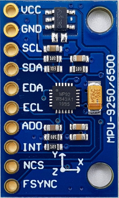
The MPU-9250 is a System in Package (SiP) that combines two chips: the three-axis MPU-6500 gyroscope, which is also a three-axis accelerometer, and the AK8963, which is a three-axis magnetometer. So the MPU 9250 performs the functions of several sensors at the same time: it is a gyroscope, accelerometer and magnetometer.
Let us dwell a little on each of them.
The gyroscope is a sensor that responds to changes in the orientation angles in space. In the drone, it is used to stabilize the position of the device in the air and protect it from the wind.
The accelerometer compares the acceleration projection of an object to the acceleration of gravity and is able to measure the linear velocity of the object and, together with the gyroscope, its position in space.
A magnetometer is a device for measuring the intensity of the nearest magnetic field acting on an object (the name of the sensor speaks for itself).
According to some sources, the MPU 9250 is the smallest nine-axis sensor in the world. This indicates the high performance of the chip, which is provided using CMOS MEMS ( microelectromechanical systems ) technology.
The case of the unit consists of two smaller crystals, one of which is responsible for the gyroscope and accelerometer and the other for the magnetometer. The data from these crystals are processed by the integrated signal processor DMP (Data Management Platform) using Motion Fusion algorithms and transmitted via the I 2 C or SPI interfaces .
In addition to high performance, the unit is quite popular among electrical engineers and those who love remote control devices, while also having low power consumption and cost.
Principle of operation of the accelerometer
An accelerometer measures the rate at which the speed of an object changes over time, also known as acceleration. With an accelerometer, you can also understand the angle of inclination of the sensor relative to the ground.
An accelerometer has tiny crystals that are pressurized when vibrations occur. From this pressure, a voltage is generated that gives an indication of any acceleration. The unit of measurement for acceleration is the measure per second squared (m / s ^ 2). But as the accelerometer sensors express measurements in “g”, a “g” is the value of the earth’s gravity equal to 9.8 meters per second squared.
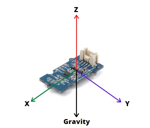
For example, in a 3-axis accelerometer such as the MPU9250 accelerometer sensor, when mounted horizontally with the Z axis up, the output of the sensor Z axis = 1 g or 9.8m / s 2 while X and Y = 0 This is due to the force of gravity perpendicular to the X and Y axes and thus does not affect them.
From this data, with simple trigonometric mathematics, one can calculate the angle of the sensor and consequently the construction on which the sensor is attached.
Principle of gyroscope operation
The gyroscope measures the speed of rotation or the rate of change of angular position over time. Its operation is based on the Coriolis effect.
When a mass moves in a certain direction at a certain speed and an external angular rotation rate is applied, then a force will be detected which the sensor will detect.
The gyroscope outputs are in degrees per second
If we know the initial angle of the IMU, we can add the value given to us by the gyroscope to know the new angle at any time. Suppose we start the IMU from 0 °. If the instrument gives us a measurement every second and marks 3 on the X axis, we will have the angle with this simple formula:
AngleX = PreviousAngleX + GyroDataX * elapsedTime
AngleY = PreviousAngleY + GyroDataY * elapsedTime
Where elapsedTime is the time elapsed each time this formula is calculated within the loop, PreviousAngle is the angle calculated the last time this formula was called and GyroData is the y or X angle reading of the gyroscope.
The magnetometer
The MPU-9250 chip includes the AK8963 which is the magnetometer. This may know the orientation relative to the magnetic north, similar to how a hand compass works. Built-in 16-bit ADCs simultaneously sample the 3 drive axles (X, Y, Z).
The magnetometer can be calibrated automatically using the magcalMPU9250 function (float * dest1, float * dest2) and calibrates the magnetometer as you move the sensor in figure eight. Saves the maximum and minimum readings and takes the average.
Construction
The construction is a continuation of the previous one I did with the two servomotors . To this we will add the MPU-9250 sensor. The most important thing for the construction is the software that we will write so that the movement in the servomotors is now controlled by the sensor and not by the potentiometers.
The following figure shows the connection circuit of the sensor with the Arduino UNO.
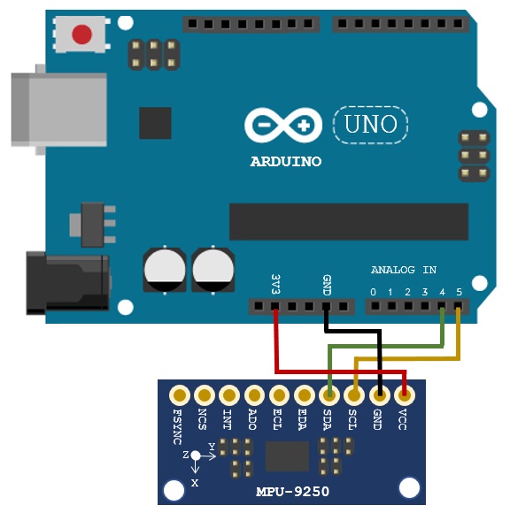
The connection is made with the I2C (Inter-Integrated Circuit) bus, a communication protocol with two conductors that the sensor has.
For the sake of simplicity I will use three of the nine axes of the sensor. I will only use the accelerometer for the x, y and z axes. The drive will be in two levels perpendicular to each other and will be provided by the two servomotors. As you can see on the sensor board the manufacturer has marked the axes. The axes are parallel to the planes of motion, each with a plane of motion.
The purpose of the construction is to keep the sensor in a horizontal plane as well as to turn the support level of the construction.
The sensor is mounted on a stand that is horizontal at rest. We place it so that it is parallel to the support base. Then as I rotate the stand I will notice how the servomotors bring the sensor to a horizontal position.
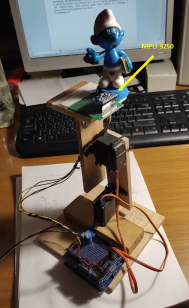
From the basket with my grandchildren’s toys I took a smurf, Spirtoulis, and put it on the platform with the sensor. Spirtoulis’ upright posture immediately indicates that the sensor is horizontal.
The photo below shows the construction and the video I give you at the end of the article shows the operation of the construction.
Programming
My advice is that the libraries you use for the Arduino IDE are in the folder of the project you are working on. The library I used for the MPU9250 is the Bolder_Flight_Systems_MPU9250 which if you do not have it installed is easy to download from the internet.
Then I quote the code I wrote which you can download from here
//Author : Manolis Aristovoulidis
//This program uses an MPU-9250 and two servo motors
//with the program running the servo motors always keep the sensor in a
//horizontal position


#include <Wire.h>
#include <MPU9250.h>
#include <Servo.h>


Servo servo_x;  // creating a servo object to control the servo
Servo servo_y;

int val_x = 95;     // variable for the movement angle of servo_x
int val_y = 100;    // variable for the movement angle of servo_y

 // an MPU9250 object with the MPU-9250 sensor on I2C bus 0 with address 0x68
 MPU9250 IMU(Wire,0x68);


int status;

 //Acc Variables

float rad_to_deg = 180/3.141592654;           //This value is for pasing from radians to degrees values
float Acc_rawX, Acc_rawY, Acc_rawZ;           //Here we store the raw data read
float Acc_angle_x, Acc_angle_y;               //Here we store the angle value obtained with Acc data

float Total_angle_x, Total_angle_y;           //Here we store the final total angle

int x_tilt = 0;
int y_tilt = 0;
int i;


void setup() {
  // serial to display data
  Serial.begin(115200);
  while(!Serial) {}

  servo_x.attach(4);    //attaches the servo to pin 4 of the servo object
  servo_y.attach(5);    //attaches the servo to pin 5 of the servo object

  //rotation of servo motors
  servo_x.write(val_x);   //After experimentation this is the
  servo_y.write(val_y);   /horizontal position for the MPU9250 base

  delay(1000);

  // start communication with IMU
  status = IMU.begin();
  if (status < 0) {
    Serial.println("IMU initialization unsuccessful");
    Serial.println("Check IMU wiring or try cycling power");
    Serial.print("Status: ");
    Serial.println(status);
    while(1) {}
  }
  /* Default values of MPU9250
   * accel range to 16G as default
   * gyro range to 2000DPS as default
   * bandwidth to 184Hz as default
   * sample rate divider to 0 as default
   *
   */
   // αναμονή για το calibration που προκαλει η IMU.begin()
  delay(3000);
}

void loop() {

  IMU.readSensor();
  Acc_rawX = IMU.getAccelX_mss();
  Acc_rawY = IMU.getAccelY_mss();
  Acc_rawZ = IMU.getAccelZ_mss();


  /*---Y---*/
  Acc_angle_x = (atan((Acc_rawY)/sqrt(pow((Acc_rawX),2) + pow((Acc_rawZ),2)))*rad_to_deg) ;
  /*---Y---*/
  Acc_angle_y = (atan(-1*(Acc_rawX)/sqrt(pow((Acc_rawY),2) + pow((Acc_rawZ),2)))*rad_to_deg) ;


////////////////////////////////////// Tilt angle and filter /////////////////////////////////////


  Total_angle_x = 0.94 *Total_angle_x  + 0.06*Acc_angle_x;
  Total_angle_y = 0.94 *Total_angle_y  + 0.06*Acc_angle_y;

  x_tilt = (int)Total_angle_x ;
  y_tilt = (int)Total_angle_y ;

//********************* Calculating return movement on the X axis **************************************
  if(x_tilt > 1){
    val_x--;
  }
  if(x_tilt < -1){
    val_x++;
  }
  if(val_x > 180){val_x = 180;}
  if(val_x < 0){val_x = 0;}
//********************* Calculating return movement on the Y axis ****************************************
  if(y_tilt > 1){
    val_y++;
  }
  if(y_tilt < -1){
    val_y--;
  }
  if(val_y > 180){val_y = 180;}
  if(val_y < 0){val_y = 0;}

//******************* Servo motor movement at an angle between 0-180 degrees******************************************

  servo_x.write(val_x);   // sets the servo position to the scale value
  servo_y.write(val_y);   // sets the servo position to the scale value

  delay(50);
}
By using two servomotors, the platform that supports the MPU9250 motion sensor is always kept in a horizontal position. No matter how I turn the base on which the whole mechanism rests, the platform returns to a horizontal position.
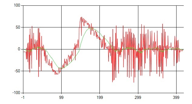
In the image below you can see the values given by the accelerometer of the sensor while moving, while trying to balance the value to zero for the x-axis. The red line shows the sensor values and the green line shows the values given by the smoothing filter on line 166 of the program and which values drive the servomotor x.
Construction in operation is shown here .