
Step Motor
A stepper motor is a type of DC motor that rotates in steps. When an electric current is applied, the motor rotates gradually and the speed of rotation depends on the “speed” at which you apply the electric current to its coils. The direction of rotation depends on the activation sequence of the motor coils. The angle of a step depends on how many windings the motor has.
Step Motor Types
Generally speaking, there are two types of stepper motor, unipolar and bipolar.
Bipolar motors have 4 wires connected to the two separate coils inside the motor – one pair for each coil.
There are also two types of unipolar motor – those with 5 wires and those with 6 wires.
6-wire motors can also be referred to as hybrid motors. They are similar to 4-wire bipolar motors and just have an extra wire connected to the center of each of the coils. If you want to use a 6-wire motor in bipolar mode, just ignore the wires connected to the centers of the coils.
5-wire motors cannot be driven by a driver designed for a bipolar motor. An example of a 5-wire motor, which we develop next, is the small 28BYJ-48 motor that can be seen in many Arduino projects and usually uses a ULN2003 chip as a driver.
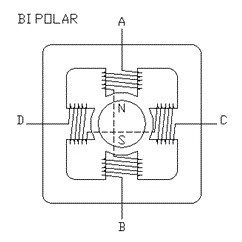
The stepper motor consists of a stator (coils) and a rotor (permanent magnets), see BIPOLAR diagram. The bipolar stepper motor contains independent coils (without being connected to each other by a medium tap), while in the unipolar stepper motor the coils have a medium tap. Usually the two middle taps are connected together and connected to the positive pole of the source. So the bipolar motor has four wires while the unipolar has five.
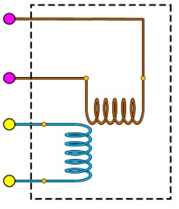
In a bipolar motor, to reverse the magnetic field of the coil, we must reverse the polarity of the voltage at its ends.
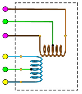
In the unipolar motor if the positive pole of the voltage is applied to the middle tap of the coil, then to reverse the magnetic field of the coil it is sufficient to select the other end of the coil connection for grounding. The circuit is much simpler, but the power of the motor is half, since each step operates half the coil.
Step motor specifications
Data sheets usually list coil current, coil resistance, rated voltage and holding torque, and steps per revolution. For example, for a motor these values are current 1 Amp, resistance 2.7 Ohms, voltage 2.7 Volts, torque 1.4 Kg-cm and 200 steps per revolution.
The nominal voltage is irrelevant for practical purposes. The important element is the rated current.
Rated current is normally the current per coil, and when stepper motor currents are quoted for driver boards, this is usually a value per coil.
Holding torque is the torque available to resist rotation while the motor is stationary. Available torque will decrease as speed increases.
Some manufacturers provide graphs showing how torque varies with speed.
Operating voltage
Stepper motors are very different from regular DC motors.
In a DC motor you control the current to control the speed of the motor. The usual way to control the current is to vary the voltage – perhaps using the Arduino analogWrite() function to control a pulse width modulated current supply to the motor.
Stepper motors almost draw their full current all the time, even when stationary – so they resist moving from their current position. This means they are very inefficient.
For practical purposes, the rated voltage of a stepper motor is irrelevant. It is the voltage that will drive the rated current through the coil when the motor is stationary based on Ohm’s law e.g. 2.7v = 1A * 2.7 Ohms. However, once the motor starts moving, the combination of the inductance of the coils and the back-emf created by the motion will prevent the rated voltage from producing the rated current.
For this reason stepper motors usually run at a much higher voltage. This, in turn, means that a specialized stepper motor driver board is needed that can limit the current to what the motor can take. If the current is not limited, the high voltage will quickly destroy the motor.
Operating voltage
Here I have chosen to give an example of stepper motor operation using the 28BYJ-48 5v shown in the figure below.
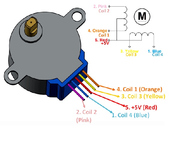
I will use an Arduino Uno to program the motor’s movement and a ULN2003 Darlington driver to provide the required current for its movement.
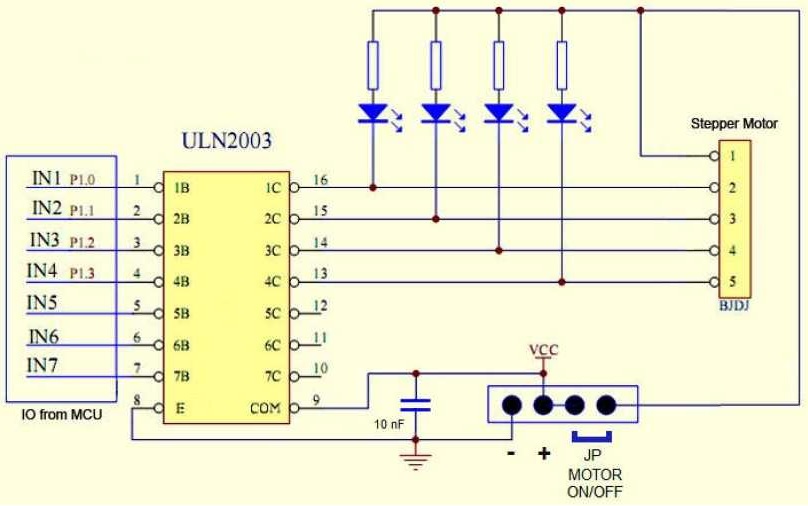
The ULN2003 groups 7 Darlington transistors into a single integrated circuit, which makes it possible to supply a motor with much higher current than what a microcontroller like the Arduino can provide.
IMPORTANT: The ULN2003 works great for unipolar stepper motors (those with 5 or 6 wires), but it is not at all designed to drive bipolar stepper motors (those with only 4 wires).
For a bipolar motor, we will need to use another circuit, such as an L298N dual H-bridge based on the very popular L298 Dual H-Bridge Motor Driver Integrated Circuit.
A few words about the 28BYJ-48 5v motor
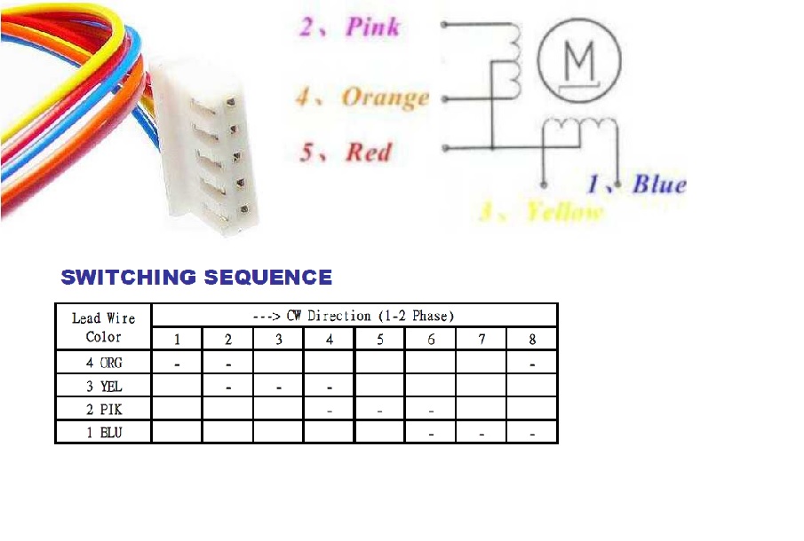
Above we showed the color chart of the motor cables. However, it must be said that this motor has a built-in speed reducer, as shown in the figure.
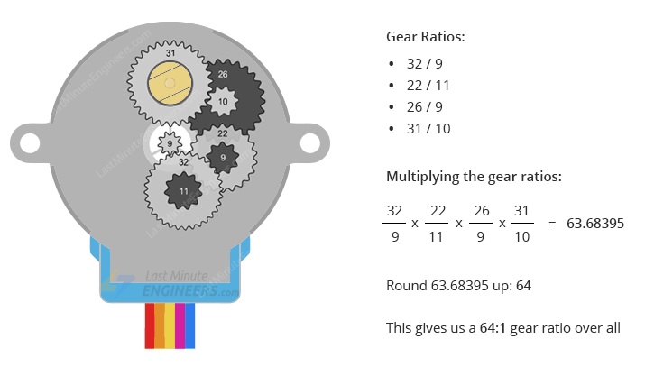
According to the datasheet, when the 28BYJ-48 motor is operating in full-step mode, each step corresponds to a rotation of 11.25°. This means that there are 32 steps per revolution (360°/11.25° = 32).
In addition, the motor has a 1/64 speed reduction ratio. (It is actually 1/63.68395, but for most applications 1/64 is a good approximation)
This means that we actually have 32*63.68395 steps per revolution = 2037.8864 ~ 2038 steps!
Driver for 28BYJ-48 5v motor
In the image below we see the schematic diagram of the ULN2003 driver for the 28BYJ-48 motor.
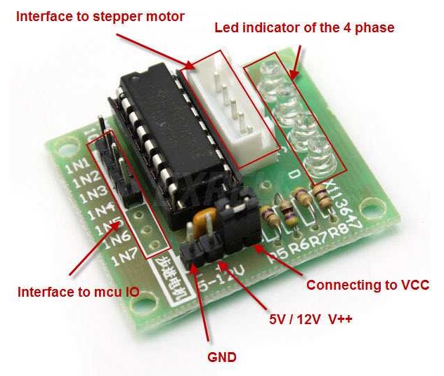
While in this image we see the board that implements the driver for the 28BYJ-48 motor.
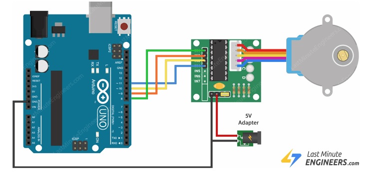
And finally, in the image below we see the connection of the Arduino UNO with the driver and the connection of the driver with the motor.
Programming the 28BYJ-48 stepper motor.
In the following image we see the order in which the motor coils should be powered so that it makes one rotation in the direction the clock moves.
This switching in the coil connections is ensured by the program we write for the Arduino and which I quote below.
Controlling a stepper motor with Arduino using the L298N Driver
Programming the 28BYJ-48 5v stepper motor so that it makes one full turn right and one full turn left.
//define the pins I will use to connect the motor

#define IN1 8
#define IN2 9
#define IN3 10
#define IN4 11
int Steps = 0;
boolean Direction = true;
void setup() {
    Serial.begin(9600);
    pinMode(IN1, OUTPUT);
    pinMode(IN2, OUTPUT);
    pinMode(IN3, OUTPUT);
    pinMode(IN4, OUTPUT);
}
void loop() {
    for(int i=0; i<4076; i++){
      stepper(1);
      delayMicroseconds(1200);
}
Direction = !Direction;
}

void stepper(int xw) {
  for (int x = 0; x < xw; x++) {
    switch (Steps) {
      case 0:
        digitalWrite(IN1, LOW);
        digitalWrite(IN2, LOW);
        digitalWrite(IN3, LOW);
        digitalWrite(IN4, HIGH);
        break;
      case 1:
        digitalWrite(IN1, LOW);
        digitalWrite(IN2, LOW);
        digitalWrite(IN3, HIGH);
        digitalWrite(IN4, HIGH);
        break;
      case 2:
        digitalWrite(IN1, LOW);
        digitalWrite(IN2, LOW);
        digitalWrite(IN3, HIGH);
        digitalWrite(IN4, LOW);
        break;
      case 3:
        digitalWrite(IN1, LOW);
        digitalWrite(IN2, HIGH);
        digitalWrite(IN3, HIGH);
        digitalWrite(IN4, LOW);
        break;
      case 4:
        digitalWrite(IN1, LOW);
        digitalWrite(IN2, HIGH);
        digitalWrite(IN3, LOW);
        digitalWrite(IN4, LOW);
        break;
      case 5:
        digitalWrite(IN1, HIGH);
        digitalWrite(IN2, HIGH);
        digitalWrite(IN3, LOW);
        digitalWrite(IN4, LOW);
        break;
      case 6:
        digitalWrite(IN1, HIGH);
        digitalWrite(IN2, LOW);
        digitalWrite(IN3, LOW);
        digitalWrite(IN4, LOW);
        break;
      case 7:
        digitalWrite(IN1, HIGH);
        digitalWrite(IN2, LOW);
        digitalWrite(IN3, LOW);
        digitalWrite(IN4, HIGH);
        break;
      default:
        digitalWrite(IN1, LOW);
        digitalWrite(IN2, LOW);
        digitalWrite(IN3, LOW);
        digitalWrite(IN4, LOW);
        break;
      }
    SetDirection();
    }
  }
void SetDirection() {
    if (Direction == 1) {
      Steps++;
    }
    if (Direction == 0) {
      Steps--;
    }
    if (Steps > 7) {
      Steps = 0;
    }
    if (Steps < 0) {
      Steps = 7;
    }
  }
In this example, I give you a simple code to understand the operation of stepping for these motors. Of course, the Arduino IDE environment includes libraries that greatly simplify the programming of stepper motors and have several examples.
Such libraries are the stepper library that you declare in the program with #include . The stepper library is used for block programming. That is, the microcontroller will wait for the number of steps that the motor will take to finish before going to the next command in the program.
The AccelStepper library that you declare with #include allows you to accelerate or slow down the movement of the stepper motor. It is also a non-block programming library. That is, the microcontroller will NOT wait for the number of steps that the motor will take to finish before going to the next command in the program.